
In this post, you will learn the concept of the connections of the Zener diodes in series and parallel. I explain the total voltage and watt power calculation in different combinations of Zener diodes in series and parallel.
I will also explain the difference between theoretical and practical values of the voltage and current distribution, and also the total useful watts of the Zener didoes.
We can connect the Zener diodes in series and parallel to get more voltage and watts in series, and better reliability in parallel. But the total useful watt will be less than the calculated value.
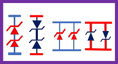
Refer to Figure 1 above. Two Zener diodes can be connected in series and parallel in different ways in circuits. The above circuit shows the four methods of connection of the Zener diode. These connections depend on the applications of the Zener diodes and circuits.
Now, I will explain one by one with calculations and also the total watts of the Zener diodes connected in series and parallel.
Zener diodes connection in series
Refer to Figure 2. The two Zener diodes are of 10 volts and 1-watt type and are in series. If you divide 1 watt by 10 volts, then we get a 0.1 Ampere current rating.
However, generally, we concentrate on the voltage and watts of the Zener diode. Voltage and watt rating are more useful in real applications.
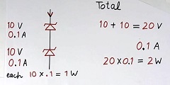
Now, if we connect two 10-volt Zener diodes in series as above, then the total voltage will be 20 volts.
But the same current flows in both Zener diodes, so the total current rating remains 0.1 amperes. And total watts will be 20X0.1 = 2 watts.
So with the above arrangement, we get a total of 20 volts, 2 watts. So connecting two Zener diodes in series doubles the watts and voltage.
Zener diodes of different voltages in series
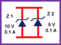
Now, suppose we connect two Zeners of different voltages in series, one Zener of 10 volts 1 watt, and another one of 5 volts 1 watt, as an example. Then the calculation will be as follows:
Refer to Figure 3. The current rating Z1 will be 0.1 amp same as above.
The current rating of Zener diode Z2 will be 1W/5V = 0.2 amperes.
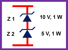
So, the current allowed in Z1 is 0.1 amperes. The current allowed in Z2 is 0.2 amperes. So the maximum current allowed with both diodes in series is 0.1 ampere. Because more than 0.1 amperes in the circuit will damage the Zener Z1.
Total voltage = 10 + 5 = 15 volts, and maximum current 0.1 amperes.
Then, the total watts will be 15×0.1=1.5 watts
So in this arrangement, the total watts will be 1.5 watts, and not 2 watts.
And the loss in Z2 at 0.1 amp will be 5×0.1 = 0.5 watts. So you can select Z2 of 0.5 watts type theoretically.
Zener diodes connection in series facing each other
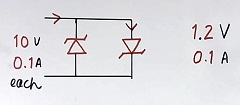
Now, refer to Figure 4. Here, two Zener diodes of 10 volts and 1 W, are in series but face to face. The cathode of both Zeners is connected to each other.
If current flows from top to bottom, then the top Zener is forward-biased, and the voltage drop in this Zener will be about 1.2 volts. (As per the datasheet, the maximum forward voltage drop in Zener is 1.2 volts, but it can be less, also as per the current flow.
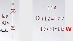
So the total voltage across both the Zeners is = 1.2 + 10 = 11.2 volts.
At 0.1 amp current flow, the total watts will be 11.2×0.1 = 1.12 watts.
Zener diode connection in parallel
Now refer to Figure 5. The circuit in Figure 5 shows the parallel connection of the Zener diodes with the Zener diode in series. Two 10-volt, 1-watt, and 0.1-amp Zener diodes are connected in parallel. In this case, the voltage remains the same, but the current will double.
Total watts will be 10×0.2 = 2 watts theoretically under ideal conditions. But 0.1 + 0.1 = 0.2 amperes, 2 watts is not practical.
The voltage of zener diodes has a tolerance of =/- 10 %. So the voltage of each zener diode can be anything between 9.5 volts and 10.5 volts. The total current will not be (0.1 + 01 ) 2 A
This is due to the fact that all Zener diodes have some tolerance in voltage, say 5 percent. So the voltage of each Zener can be anything between 9.5 volts to 10.5 volts. This depends upon Zener to Zener and also on the current flowing. This is due to asymmetry, as no two Zener diodes are identical.
For example, if the voltage of one Zener diode is 9.5 volts, another one has 10.5 volts. If we connect them in parallel, then most of the current will flow in 9.5 volts type Zener.
There will be very little current in the Zener of 10.5 volts type. So, there is hardly any advantage in the parallel connection of the Zener diodes to increase the total watts.
So the parallel connection of the Zener diodes does not give any useful extra watts (the only series connection has advantages). But still, we can use it with no disadvantage. You can also use them and check, maybe that particular Zener diodes have fewer voltage variations. Then the parallel connection will have some use.
The Zener diodes in parallel may be useful if a heavy current for a short time flows in the Zener diodes. Then, both the Zener diodes in parallel may share part of the current.
So, the Zener diodes in series are more practical than in parallel connection.
Zener diodes connection in anti-parallel
Now, refer to Figure 6. Both Zener diodes are in parallel but back to back (antiparallel).
If current flows from top to bottom, then full current flows through the right side Zener diode, as it has a drop of 1.2 volts only. No current flow in the left side diode. So the voltage across the parallel circuit will be just 1.2 volts.
Zener diodes in parallel to improve reliability
Suppose we connect two Zener diodes in parallel, and one of them fails and becomes open after burning or otherwise.
In that case, another Zener diode will take over, and the circuit will continue to work. This will improve the reliability of the system or circuit.
“Zener diodes connected in parallel may not give watts advantages, but they improve the reliability of the system.”
Advantages of Zener diodes in parallel
As discussed above, the advantages of Zener diodes connected in parallel are:
- To improve the reliability of the circuit in case of the failure of one Zener diode
- Share some current, in case of heavy current, for a short time.
- In a few cases, if the voltage of both Zener diodes is close to each other, then improving the total watts to a limited extent.
Extra knowledge as per experience – watt selection of Zener
In the above various examples of Zener diodes in series and parallel, we calculated the calculation of watts of the Zener diode. At the beginning of my job (without experience), I followed the above calculation.
However, just after my 1st project, I realised that there is something more than the above calculation, as many of the Zener diodes started giving off smoke in a few electronic modules total of 10 in number. Here, Zener diodes were standalone and neither in series nor in parallel.
When I made one card, it worked well. But when the production department manufactured 10 numbers of the same design, there were a few failures. I am going to share with you the facts.
We take the watts or current rating of Zener diodes (or even of other electronic components) from the data sheets of the components. However, there will be many fine prints about the maximum rating in the datasheet application notes, especially on ambient temperature, cooling, and a few other circuit design conditions.
So, the watts limits of the Zener didoes will have to be derated due to the following reasons:
- Derating due to limits as per application notes and data sheet (ambient temperature, cooling, mounting arrangement, etc)
- Further, our calculation itself may not be 100 percent accurate due to a lack of knowledge or unknown operating conditions.
- Further, there is an unwritten law of reliability (left to experience)
- For a better theoretical MTFR (mean time failure rate)
So, considering all the above factors, actual useful watts (derating) and current of the Zener diodes, standalone or in series,s will be much less than the specified values, and very little or no advantage of watts in parallel connections.
One watt Zener may not take more than 0.5 watts, considering many limitations. This is just my experience and the rule of thumb.
After doubling the watts of Zener diodes in my circuit, all electronic modules were working properly even in a hot chamber.
Try checking your electronic cards by keeping them ON inside a hot chamber at 50 degrees for 48 hours (this test is done as a type-test for quality control). You will know the results. This chamber temperature varies with applications.
Do it yourself – ambient temperature of the laptop
In India, in many places, the ambient temperature goes to more than 45 degrees. Just check the maximum ambient temperature allowed for the laptop as per the datasheet, you are going to buy or have bought already. Do it yourself. You will learn something more.
If you want more knowledge, then watch the video below:

Further, read my special article on “How to use an open circuit CT transformer”
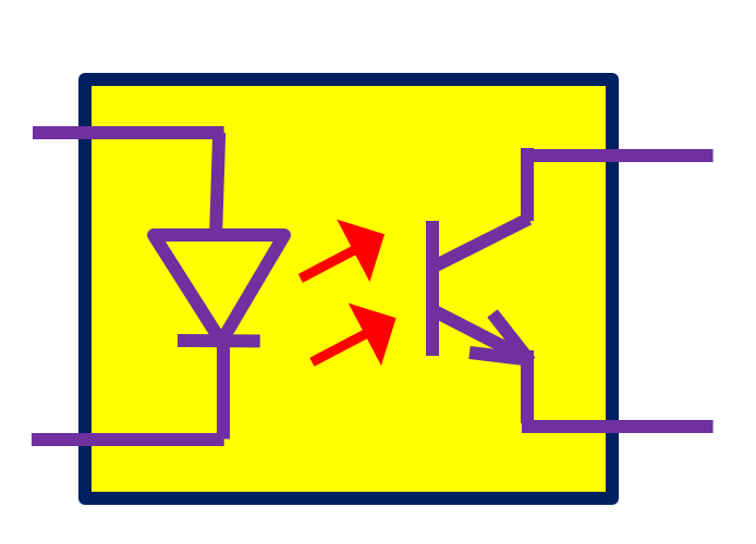
Also, read the article What is an optocoupler and how it works?
Keep learning and reading Which motor is used in the electric train engine?
Further, read What is AFDD AFCI breaker?
I hope that you enjoyed the article on “Zener diodes in series and parallel”
If you like more technical videos and hand-drawn diagrams from an industry professional, then subscribe to my YouTube channel “G K Agrawal”.

About the Author – G K Agrawal is a retired Sr. DGM from BHEL and an Electrical & Electronics engineering professional with extensive industry and R&D experience. Through this blog and YouTube channel, he shares practical insights to help students and professionals understand real-world engineering applications. Read more about him here.
Great explanation