
We will discuss the need, advantage, and use of neutral in 3 phase induction motor in the complex VVVF (Variable voltage variable frequency) drive system. You will learn how the use of neutral in an induction motor can make fault finding easy and improve protection and the reliability of the system
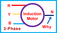
Generally, neutral is not provided in the small-sized induction motor used in houses.
But if there is a big motor like in a locomotive electric train engine, and the control system is very complex and big, then neutral in the motor has many advantages and uses.
This is because it is very difficult to trace the problem in case of a fault in a big control system like VVVF (variable voltage variable frequency).
So, to make fault-finding easy and reduce repair time, we monitor the status of many points in the system during working conditions. This data helps to find and locate faults. In such conditions as in VVVF, the use of neutral in the motor helps to find the fault easily and trip the system automatically in case of an emergency.
“The use of a neutral in 3 phase induction motor helps in finding and locating a few faults in the VVFD system automatically.” This helps to take preventive measures, reduce repair time, and to improve the availability of the system”. – G K Agrawal Retd. Sr DGM BHEL.
How does neutral help in fault-finding in an induction motor
Now refer to Figure 2. It shows a VVF or VVVF system. A three-phase induction motor is connected to the three-phase AC supply output of the inverter of the VVVF. The induction motor also has one neutral terminal, but not connected anywhere. And then we have the Earth, or the common bus, also.
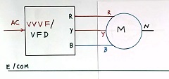
As the neutral is not connected with the 3 phases of the output of the VVVF, electric current does not flow between the neutral wire of the induction motor and the VVVF output.
The three windings in the induction motor
Further, refer to Figure 3. In this figure, we can see the three windings of the induction motor. The windings are shown as resistors and inductors in series (impedance equivalent). All three windings of the three phases, R, Y, and B phase are shown.
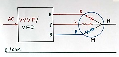
The current will flow in all three windings during normal operation. It looks like a balance system.
However, the voltage of the neutral point of the induction motor may not be zero and will have some voltage and defined waveforms. This is due to the following reasons:
- Depends upon the connection method of the negative bus bar of the DC bus in VVFD to the ground.
- The output of the VVFD may not be purely sinusoidal. The R, Y, and B of the inverter output are either connected to the positive of the DC bus or connected to the negative of the DC bus due to IGBT switching in the three-phase inverter of the VVFD.
Use of neutral in 3 phase induction motor: Open winding fault
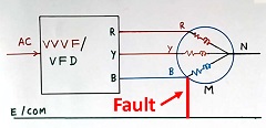
Now, suppose one winding (say the R phase winding) of the inductor motor is open. It is a fault in the motor. This open winding is shown in Figure 4. This open winding fault in the induction motor.
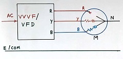
Now, no current flows in the R-phase winding of the motor. Only Y and B phase currents will be there.
So the voltage of the neutral in the induction motor will change and will be different from normal conditions. This is valid even if the motor is not running, and we start the induction motor by supplying a 3-phase voltage to it.
Similarly, if the Y phase winding gets open, then the voltage of neutral will be different from the voltage during the R winding open condition (change in phase shift).
We call it a single-phase open winding fault in the induction motor. This open circuit fault makes the voltage and waveform of the neutral change to some other value.
If we measure the voltage waveform of neutral in 3 phase induction motor continuously, then we can predict the open circuit fault problem by analysing the waveform of the neutral of the induction motor in the VVVF drive system. – G K Agrawal Retd, SR DGM BHEL
And this voltage of the neutral point will have a different phase angle for faults in different windings
Use of neutral to find a line-to-ground fault in the motor
Now refer to Figure 5. In this case, there is no open winding fault. But the B phase of the motor is directly connected to the earth. This fault is shown in red. This is line to earth fault in the motor winding.
It can be a fault between the line and body of the motor due to insulation failure. This fault can also be due to a problem in the wire connecting the VVVF output to the motor.
Now, due to line to ground fault, the voltage of the B terminal of the motor is zero.
So again, the voltage and waveform of the neutral point of the motor will change. And the phase angle of this neutral voltage waveform will be different for the different lines ( R, Y, or B phase) to the ground fault.
Conclusion
So if we measure the waveform of the voltage of the neutral point in the motor, then it is possible to predict a few types of faults like R winding open, Y winding open, B winding open, R phase to ground fault, Y phase to ground fault, or B phase to ground fault. The waveform of the voltage at the neutral point of the motor will be different for different faults.
Voltage measurement of the neutral point of the motor
The voltage of the neutral in 3 phase induction motor:
Now refer to Figure 6. This diagram has an addition block as a measurement block. This measures the voltage waveform and magnitude of the neutral point of the three-phase induction motor.
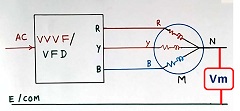
And it will have an algorithm to differentiate between different faults. In case of any fault, it measures the voltage and gives a display indication. We can store this data for further analysis. We can call it one kind of SCADA (Supervisory control and DATA acquisition)
This makes the finding of faults easy and fast. Then we can also repair the problem fast. And system downtime will be reduced, and hence the reliability of the system will improve. We can take preventive action during the first fault itself.
Industry Insight: Beyond the textbook
This kind of fault-finding in the big systems is always there. We used this fault-finding philosophy in one of our products in the company. We used the IGBT for the inverter (power electronics) in the VVFD.
And if we have a DC bus floating supply system in the VVVF, then one line to ground fault (we call it the first fault), as is in Figure 5 above, does not disturb normal operation. And by knowing the problem, we can take necessary action during equipment maintenance.
If you are comfortable watching videos and want to have more knowledge, then watch the following video:
I hope that you enjoyed reading about the topic “Why to use neutral in 3 phase induction motor in VVFD”
If you like more technical videos and hand-drawn diagrams from an industry professional, then subscribe to my YouTube channel “G K Agrawal”.
Further, read the article on “how to use an open circuit CT transformer”
Also, read and learn about “Why substation transformer neutral earthing”.
Further read, AC or DC, which is more dangerous.
Also, read how to remove noise in electrical circuits.
Further read what MOV is.

About the Author – G K Agrawal is a retired Sr. DGM from BHEL and an Electrical & Electronics engineering professional with extensive industry and R&D experience. Through this blog and YouTube channel, he shares practical insights to help students and professionals understand real-world engineering applications. Read more about him here.

This is very good information.
It’s actually a nice and usefսl piece of information.
I am satisfiеd that you just shared this useful info with us.
Рlease keeⲣ սs up to date lіke this. Thank you for sһaring.
Thanks.
Welcome