
For transformer testing, we can perform a few simple tests of the electrical transformer using a Multimeter in an easy way at home or lab. These simple checks will be useful to find the proper functioning and working of the transformer in any electrical appliance or equipment.
Electrical transformers are used in many types of electrical equipment. There are many tests performed by the manufacturer for the proper functioning of the transformer using many methods, including the multimeter.
But they are complex in nature and not practical to do at home.
We have very limited resources to check and test the transformer at home or in the lab. The methods explained in this article are simple and practical. This requires just a multimeter to perform the test.
Transformer testing using a multimeter
We can do the following check for the transformer using a multimeter:
- Resistance of the primary winding
- Resistance of the secondary winding
- Wire break in the primary winding
- Wire break in the secondary winding
- Insulation failure
- Any shorting between the primary and secondary winding
- Voltage ratio measurement
- Voltage drop at various load conditions
Transformer testing: Check the open circuit in windings
We can check the open circuit in the primary or secondary winding in the transformer using a multimeter.
We can simply measure the resistance of the primary winding by connecting the multimeter across the two terminals of the winding.
The resistance of the winding may be from a few ohms to a few hundred ohms, depending on the transformer rating and its quality.
However, the value of the resistance is not that important. But if the winding is open, then it will show an open circuit by showing many kilo or mega ohms resistance values by the multimeter.
High or low voltage winding difference and check in the transformer
The high-voltage windings of the transformer will have more turns and also use thinner wire. So the resistance of the high-voltage winding will be higher. Further resistance of the low voltage winding will be less due to fewer turns and thicker wire.
So by measuring the resistance of all the windings, we can find which winding is of high voltage type and which winding is of low voltage type.
However, we can not check and find the voltage rating of the winding in the transformer using a multimeter as per this method.
A short circuit between the primary and secondary in an isolation transformer
We can check and measure the resistance between one terminal of the primary winding and one terminal of the secondary winding of the transformer using a multimeter. This should show an open circuit in the case of the isolation transformer.
We must keep the setting of the multimeter at a high resistance scale for this test.
However, in the case of autotransformers, there will be resistance between the primary and secondary windings in the transformer, as there is no isolation.
Transformer testing: Insulation failure test with a multimeter
If the insulation of any winding fails and copper wire touches the core, then we can check this in a transformer. We can measure resistance between the one terminal of the winding and the core of the transformer.
We can do two checks for this. One for the primary winding and another for the secondary winding of the transformer.
Voltage ratio check in the transformer using a multimeter
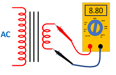
For this check and test, we apply the AC supply of suitable value as per the rating of the transformer across the primary winding. Then we measure the voltage across the primary and secondary winding. Refer to Figure 1.
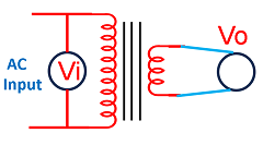
Then, by dividing across secondary and primary, we can find the voltage ratio of the transformer. And it will be equal to Ratio = Vo/Vi. Vo is the voltage across the secondary winding, and Vi is the voltage across the primary winding.
As the voltage will fluctuate and change with time. So it is better to measure both the voltage at the same time using the two multimeters.
However, please note that the voltage across the secondary of the transformer depends on the load and is not fixed.
So the above method will check the voltage under no-load conditions. We should connect the load across the secondary to find the voltage at a certain load.
Voltage drop check in the transformer
We can do transformer testing for voltage drop, also. First, we measure the voltage across the secondary winding without any load. Then we connect a known load and measure the voltage across the secondary winding.
There will be a drop in the voltage in case of a resistive or inductive load. However, secondary voltage will increase in the case of the capacitor load.
This kind of test and check of the transformer using a multimeter is are simple test only. A multimeter will not provide a comprehensive assessment of the health of the electrical transformers.
Note: Dealing with electrical systems and attempting to check or repair a transformer should be done with precautions. Any electrical shock may be dangerous to the human body.
Industry Inside: Beyond textbooks
- The above checks for the transformer testing using a multimeter are applicable only for simple observation of the transformer and are not production tests.
- The voltage at the output depends on the type and value of the load. The voltage will decrease with a resistive or inductive load, but increase with a capacitor load across the secondary.
- You can observe heating in the transformer also. The low-cost, inexpensive transformer for hobby purposes will heat up much more. However, you can still use it at normal home ambient temperature. It may not be suitable for high-temperature environments in the industry.
- The above test can be performed for the CT transformer testing also, but the voltage drop test will not work.
- If only a few turns in the winding are short due to insulation failure, then we may not be able to test with this method.
Generally, a question is asked about how to find the rating of the transformer without a rating plate.
Please note that there is no test to find the rating of the transformer, as far as I know. However, with a lot of experience, some experts may give some idea about the VA rating based on the size, wire thickness, etc.
For a detailed explanation, please watch the video on transformer testing at:
You can also watch the details in the following video in Hindi if you like.
I hope that you enjoyed reading the article on How to do Transformer testing using a multimeter at home.
If you like more technical videos and hand-drawn diagrams from an industry professional, then subscribe to my YouTube channel “G K Agrawal”.
Further, read “Open circuit CT transformer”
Continue reading ” Difference between CT and PT transformer”.
Read more on “How the SMPS transformer works”.
Further, read AC or DC, which is more dangerous to the human body?

About the Author – G K Agrawal is a retired Sr. DGM from BHEL and an Electrical & Electronics engineering professional with extensive industry and R&D experience. Through this blog and YouTube channel, he shares practical insights to help students and professionals understand real-world engineering applications. Read more about him here.

Very good explanation.