
The CT secondary open circuit use is considered fatal. But, in this article, I will discuss the use of a CT secondary open circuit in one of our industrial projects. And that worked for many years.
In this post, I explain how to use an open-circuit CT transformer (Current Transformer) or CT with an open secondary under certain conditions, with a few examples, concepts and calculations.
We can use a CT secondary open circuit transformer sometimes. I will explain the concept and use of an industrial transformer with an example.
I will also explain the equivalent electrical and flux circuit of the CT secondary open circuit condition in the CT transformer.
Further, I will also explain why high voltage comes in an open circuit. And also, what are the voltage limiting factors in the open circuit?
We know that the secondary of the CT transformer should not be left open.
However, under certain conditions, it is possible to keep it open. This is what I will explain in this post.
As it is a big article, the content of the post is given below
CT secondary Open Circuit Use: Textbook Formula
In the electrical current transformer, the electric current in the secondary is proportional to the primary current.
The voltage across the output (across the secondary winding) will be equal to the product of the electric current in the secondary and the resistor value.
VS = IS x RL
In the above formula,
- VS is the voltage across the secondary winding
- IS is the current in the secondary winding
- And “RL” is the load resistance across the secondary winding of the CT
So higher the load resistance value, the higher the voltage across the secondary winding.
The open circuit in the secondary is equal to a very high resistive load.
So very high voltage will develop across the open circuit of the secondary winding of the transformer.
But this is just a theoretical concept, as a few other factors come in during the manufacturing of the CT.
CT Secondary Open Circuit Use: Industry Insight vs Textbook
If we keep the secondary of the CT transformer open, then very high voltage may come across the secondary winding. But this concept is theoretical only and applicable for ideal conditions, as in textbooks.
Two voltage-limiting factors limit the voltage across the secondary of the open-circuit CT.
The 1st reason is due to manufacturing processes, and the 2nd reason is due to the real-life applications.
Open circuit voltage limit due to the manufacturing
The voltage across the open-circuit CT transformer is limited due to the manufacturing process as follows.
We require a very high flux level in the core for a very high voltage to develop.
And the high flux level requires a core with a large cross-sectional area.
However, the core size in the transformer is almost always just sufficient for the flux under normal operating conditions. This is to reduce the size, weight, and cost of the transformer.
As the core area of the transformer is limited, the core of the CT will saturate in case of high flux. Then the voltage will not be induced in the secondary winding.
When the current flows in the primary in the open circuit CT, then the voltage will increase 1st quite fast due to the high rate of change of the flux.
This is because the induced emf is proportional to the rate of change of flux. And full primary current will behave as a magnetising current. Then, finally core will saturate. So we may see a spike-type high voltage peak.
(This high dVS/dt was also observed by us during the testing of the transformer, as per Figure 5, explained later in this article. Our load (active load, not just a resistor) in the other two windings was such that sometimes, all windings become open type. But our core was not saturating because of the voltage limiting circuit.)
So the voltage at the secondary is always limited in open-circuit conditions in a CT transformer. This is because of the limited size of the core area, and so limited workable flux in the core.
Open circuit voltage limit due to the application
If the secondary is open, then the only primary has the electric current. This current is responsible for the flux in the core.
So, If the secondary winding is an open circuit in the CT transformer, then the CT transformer behaves like an inductor. Refer to Figure 1.
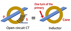
This is due to the fact that a coil over a core is like an inductor.
“In fact, all transformers with open circuit secondary are nothing but an inductor. But the value of the inductance will depend upon the type of transformer”.
CT secondary open circuit: Electrical equivalent circuit
As discussed above, a CT with an open secondary behaves like an inductor.
And the value of inductance of this inductor (of the CT equivalent) depends upon the number of turns of the primary and the size and material of the core.
Now, CT is always connected in a series of loads. So, open circuit CT is nothing but an inductor in series with a load. Refer to Figure 2.
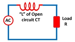
In Figure 2, if the load current is less, then the voltage across the inductor will be less.
However, if the current is very high due to the small value of the load resistor R, a heavy flux in the core will be generated, and the core of the CT will saturate.
So the voltage across the primary (across two terminals of the equivalent inductor) will depend upon the load current and inductor value.
Hence, voltage is always limited across the inductor (primary of the CT).
This kind of voltage limiting is more useful in low-voltage and low-current circuits.
If the voltage across the primary is limited, then, as per the voltage ratio and turns ratio law, the voltage across the open circuit secondary will also be limited.
So, depending on the load condition and CT construction, the voltage across open secondary is limited.
However, it does not mean that we are free to take the risk of the high voltage in an open circuit, considering the above two voltage limiting factors in the CT secondary open circuit transformer. I explained above only to understand the concept, and not to take the risks.
If you want to learn more, then you should try to simulate the above condition in a simulation software like EMTP, MATLAB, or some other simulation software.
How to use the CT secondary open circuit transformer
As discussed above, the voltage across the open secondary is high and limited by two factors. But this limited high voltage is just to protect the transformer. And CT will not work properly in such conditions.
Now I will explain the concept of how an open circuit in the secondary of the current transformer remains safe under certain conditions for normal operation.
Current transformer with two secondary windings
This explanation is as per the use of the CT transformer with one of the windings open in the secondaries, in our few projects.
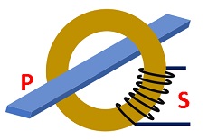
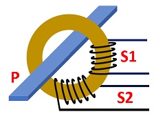
Refer to Figure 3. This CT is of bar type. So the number of primary turns is equal to one. But it has two secondary windings.
Now, suppose the CT ratio is 100/1 for each winding. So we have two secondaries, each with 100 turns.
Remember that a CT transformer is also a transformer and follows the rules and formula of the turn ratio equal to the voltage ratio.
And also, the number of turns of the two secondary windings is equal in the above example.
As both secondary windings have a common core, the flux passing through both windings is also equal.
So if the number of turns and the flux are equal in the two windings of the transformer, then the voltage across the windings will also be equal.
So, if we can limit the voltage in one secondary winding, then the voltage across the other open secondary winding will also be limited in the CT secondary open circuit condition.
Calculation of the secondary voltage
Now, refer to Figure 4. Suppose the electric current in the primary is 100 amperes.
As the CT ratio is 100/1 for each winding. So, one amp current can flow in normal conditions in the secondary.
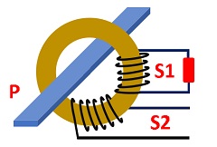
We have connected a load resistor in only one winding, S1. While another secondary winding, S2, still has an open circuit.
Now, suppose the value of the resistor connected across the secondary S1 is 10 ohms.
So the voltage across the secondary winding S1 will be equal to
VS1 = 1 X 10 = 10 volts
The number of turns in S1 and S2 is equal, and also the flux, so the voltage across S2 will be equal to S1.
So the voltage across the open-circuit winding of the CT transformer here will be just 10 volts.
Further, if the turns of S1 and S2 are not equal. For example, if the turns in the S2 are double the turns in S1, then we will get 20 volts across the S2 winding.
So, in this case, the open circuit winding S2 will not have any high voltage, and this winding can be kept open safely.
“We can use the CT secondary open circuit transformer (CT), if it has two or more secondary windings and one of them has a normal load at the output.“
CT secondary open circuit transformer: Industry Example
Refer to Figure 5. The CT transformer has one primary winding in the figure. This is for explanation purposes only in this article. Our CT was bar type without any primary at all.
A single bar in the primary acts as a primary winding of a single turn. All calculations should be done considering one turn in the primary winding.
This CT transformer has three secondary windings. And the 1st secondary winding has an open circuit.
One of the secondary windings (third winding in Figure 3) has the load across it. But in our case, this load was not a simple resistor; it was a dynamic load consisting of capacitors, resistors, transistors, gates, and op-amps.
So the load is not fixed in the 3rd winding.
The 2nd secondary winding (middle secondary winding in figure 5) has a control circuit to limit the voltage across this winding.
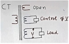
Once the voltage in this winding is limited, the voltage in the other windings always follows the turn ratio and voltage ratio rule. Even if no load across the winding.
The first winding in the secondary in Figure 3 has no load across it. But as the voltage is limited in this open winding, as per the turn ratio and voltage ratio formula. So no over-voltage will come.
If turns are not equal in all secondary windings, then the concept will also work. But the voltage across different secondary windings will depend on the turns ratio.
In fact, a small voltage control in one winding with fewer turns can control the high voltage across another winding with more turns.
Industry Insight: Beyond the Textbook
I would like to share my real project experience on CT secondary Open Circuit, Transformer Use in one of our projects.
I have discussed the application of a special transformer with a CT secondary open circuit in one of the three windings of the CT transformer.
However, it was quite a complex design of the sizing of the core.
The problem was not secondary open, as protection ensured the limited voltage.
IT was the complex variable load, which was making the calculation of the flux difficult.
So typical calculation as per the normal formula of flux value was not working. And the calculations became quite complex.
The normal textbook formula does not give accurate results in the real world.
Calculation and design
The calculation of turns, size of conductor and core required special design considerations. (We were not the transformer manufacturer, but just the user of the transformer.)
A core with a large cross-sectional area was required to make it work.
And, the transformer also became very big and expensive.
Further, those transformers worked well for years at the project site in a 220KV line.
One of the secondary windings was used as a load and was kept open.
Further, there was an electronic overvoltage protection built into the winding
This way, the voltage across all secondaries is well limited.
If you like to watch a video, then watch the video link below. It has a starting point only at the CT secondary open circuit condition in a three-winding CT.
Question and Answer
Can we keep the secondary of CT open
Normally, no, but under special conditions and design, we can keep the secondary open. The above article explains this. You should not keep secondary open in a normal design.
How does CT differ from the PT transformer
CT is used to measure current, but PT is used to measure voltage.
How accurately can the CT measure the current?
CTs are available with different accuracy classes like 2%, 1%, 0.5% etc. CT with high accuracy, like 0.5 %, will be expensive.
Where do we use high accuracy CT transformer?
For control purposes, we used high-accuracy CT in a 100MVA SVC for an unbalanced load of the ARC furnace
If you like more technical videos and hand-drawn diagrams from an industry professional, then subscribe to my YouTube channel “G K Agrawal”.
I hope that you enjoyed reading this article on CT secondary open circuit use.
Further, read the CT and PT transformer difference
Also, read How the current Transformer works
Further, read the article What is a potential transformer for more knowledge on transformers.
Read what the MOV varistor is
Further, read Why and how power factor correction?
Keep reading about how to remove electrical noise.

About the Author – G K Agrawal is a retired Sr. DGM from BHEL and an Electrical & Electronics engineering professional with extensive industry and R&D experience. Through this blog and YouTube channel, he shares practical insights to help students and professionals understand real-world engineering applications. Read more about him here.

High CT secondary voltage of an open circuit CT is not really theoretical.
If there are only two secondary terminals on the CT, you must never leave them open circuit.
Since the CT must obey ampere.turns balance, the ONLY place that the current can flow is through the excitation path. We test the excitation path as the Magnetising Curve or Excitation Curve … you can see above kneepoint the current and the voltage keeps increasing because the CT is trying to develop enough voltage to force current through an infinite impedance .. eventually that voltage will cause a BANG!
If you have three or more terminals on the secondary, you should only connect devices to one PAIR of terminals, all others left disconnected (open circuit). This is because the CT satisfies ampere.turn balance and volts/turn balance
ampere.turns means that the sum of Iprimary x tprimary must equal the sum of the ampere.turns of all the secondary windings
SO with a burden connected across one pair of terminals, a certain voltage will be developed according to Ohm’s Law V=IZ,
You therefore get a certain voltage across the other pairs of terminals and therefore current flows there also based on Ohm’s Law I=V/Z
SO you can see that the primary current ampere.turns is balanced by (Isecondary1.turns1) + (Isecondary2.turnssecondary 2) so the ratio you get out is dependant on the size of the respective burdens
Very exclusive explanation
Pingback: What is the Snubber circuit and its applications in power electronics - G K Agrawal
Pingback: Why is the electrical transformer rating is in KVA - G K Agrawal
Pingback: Electrical noise in electrical and electronics circuits - G K Agrawal
Pingback: Differences between MOSFET and IGBT - G K Agrawal
Pingback: IGBT vs Thyristor - difference - G K Agrawal
Pingback: Why high voltage sometimes present in the electricity system of the home? - G K Agrawal
Pingback: Difference between a diode and a zener diode - G K Agrawal